Robotics · Mechatronics · Prototype hardware — Fremont, CA
I build robots.
I design the parts, print and machine them, solder and wire them up, then debug the motors, power and sensors until the thing actually moves right. Below is what I've built and what broke along the way.
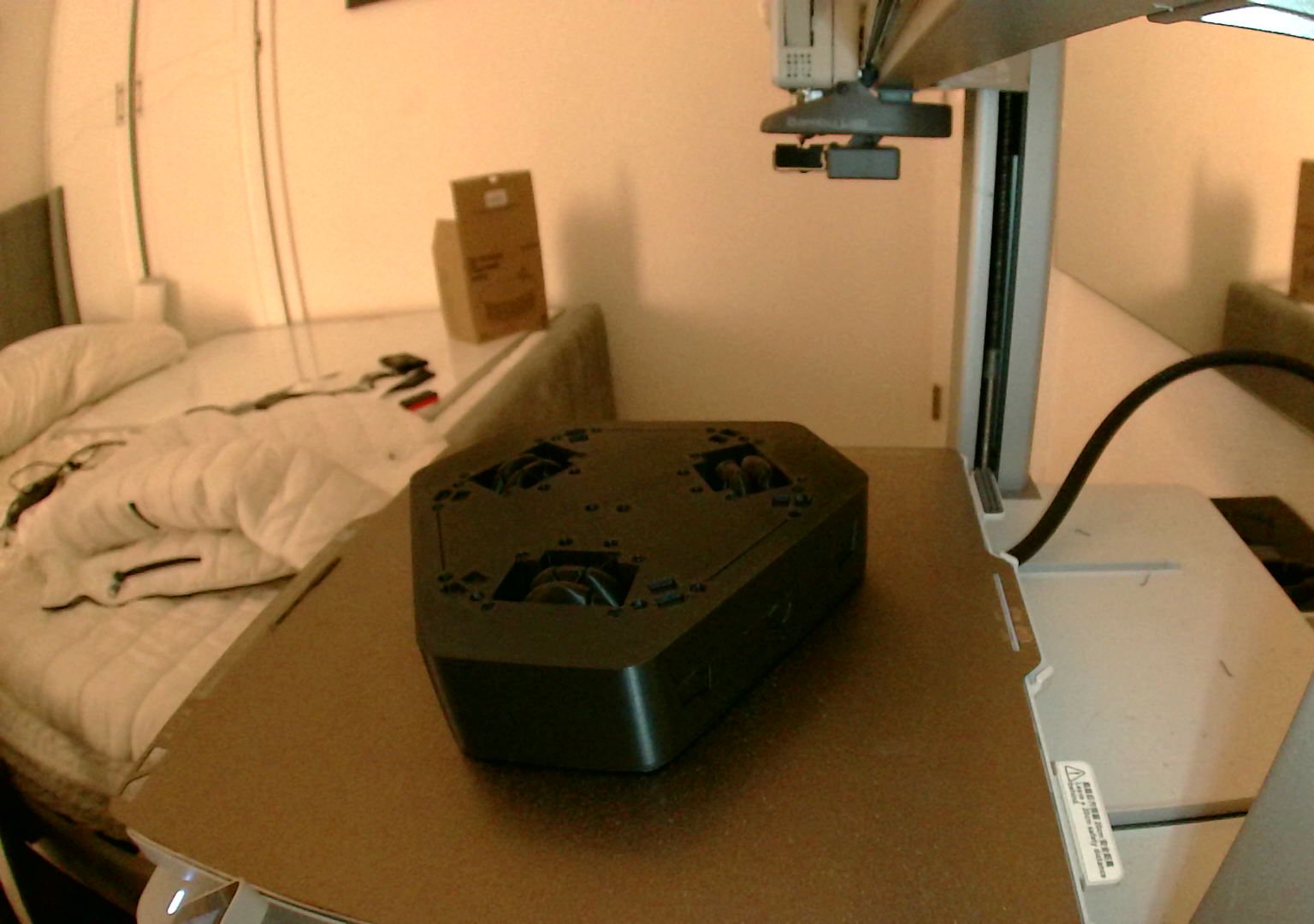
Working now · Aegis V1 · real footage, not a render
It follows the mug.
The V1 coaster drives itself back under a moving mug, then holds still as it lands. An up-facing NoIR camera tracks a retroreflective marker on the mug's base, lit by an IR LED ring.
Bring-up: the IR ring wouldn't light. Measuring across each part found the LEDs in backwards (about 4 V across each LED, 0 V across its resistor), on top of a wrong GPIO pin and a bad breadboard.
Calibration: the robot estimated its own camera-to-wheel rotation (about 115°) by driving small moves and watching how the scene shifted.
Tuned from logged data: every frame recorded. Lost tracking went from 70 times in 47 s to once in 124 s.
Tested to failure: while I turned up the acceleration, a printed wheel hub sheared. AI-assisted log analysis pointed to hard braking shocks. The software now holds through camera dropouts and coasts on faults; a braking limit and a stronger hub are next.
Software written with AI tools · wiring, measurement and testing by me · V1 build log ↓
Bring upRaspberry Pi 5 · Motoron / motor drivers · encoders · cameras · I²C · power distribution
DebugScope · multimeter · bench supply · root-causing motor, power and sensor faults
CodePython · OpenCV · Linux · Git · AI-accelerated CAD/EDA and control-software workflows
01 — Aegis V2 · latest design work: September 2026
Aegis V2
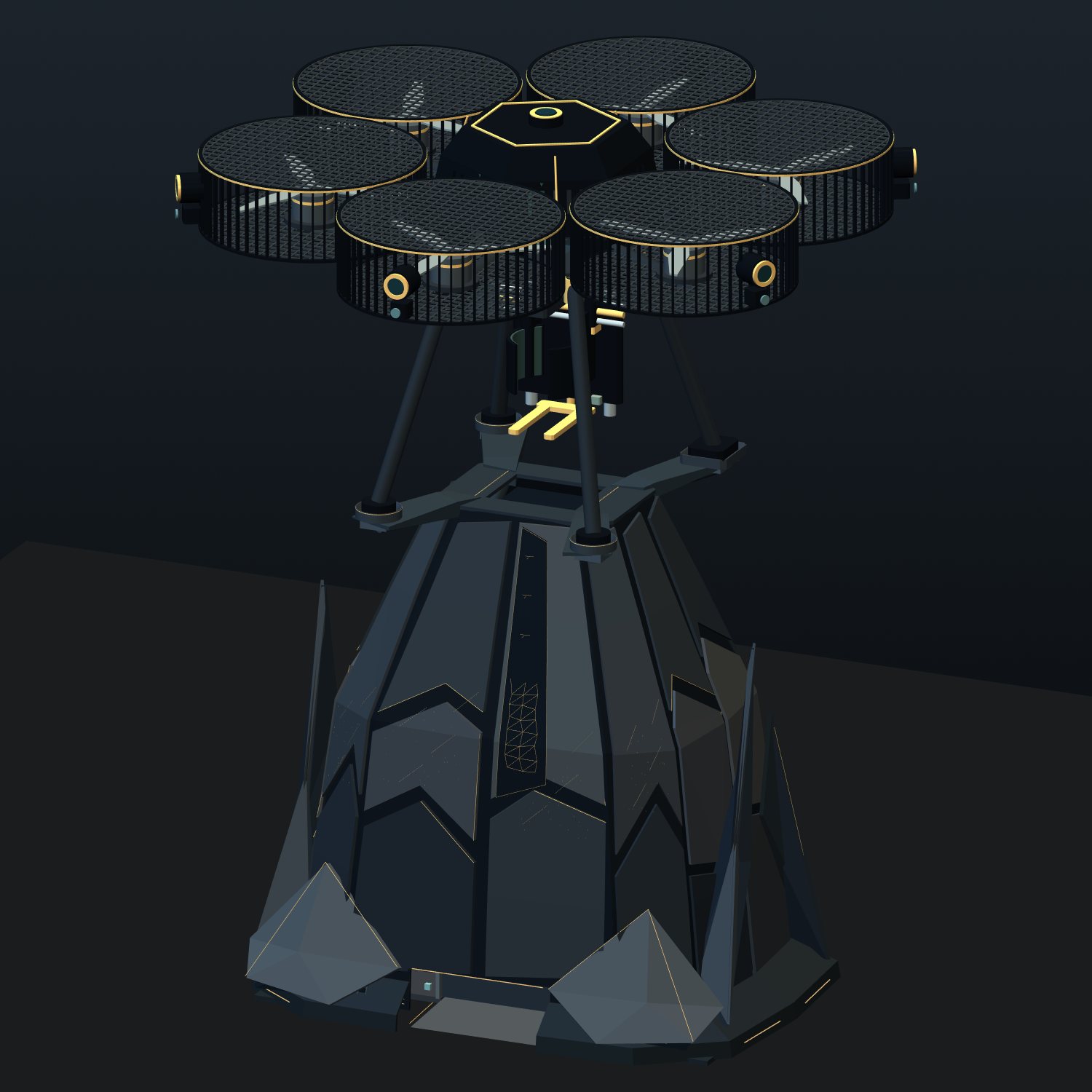
A 39 mm-tall robot coaster designed to move under a cup, respond to gestures and detect table edges. The latest work brings the enclosure, optics, floating deck and charging interface together.
CAD + analysis Design study, not a functional V2 prototype. Not being built or ordered. The working hardware is V1.
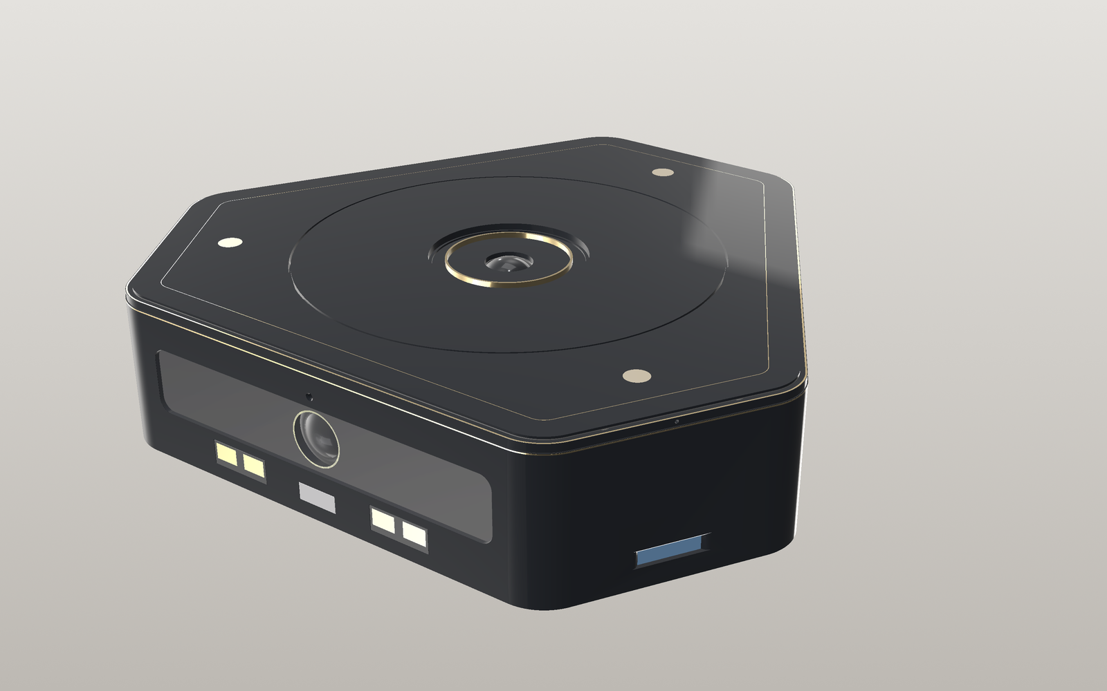
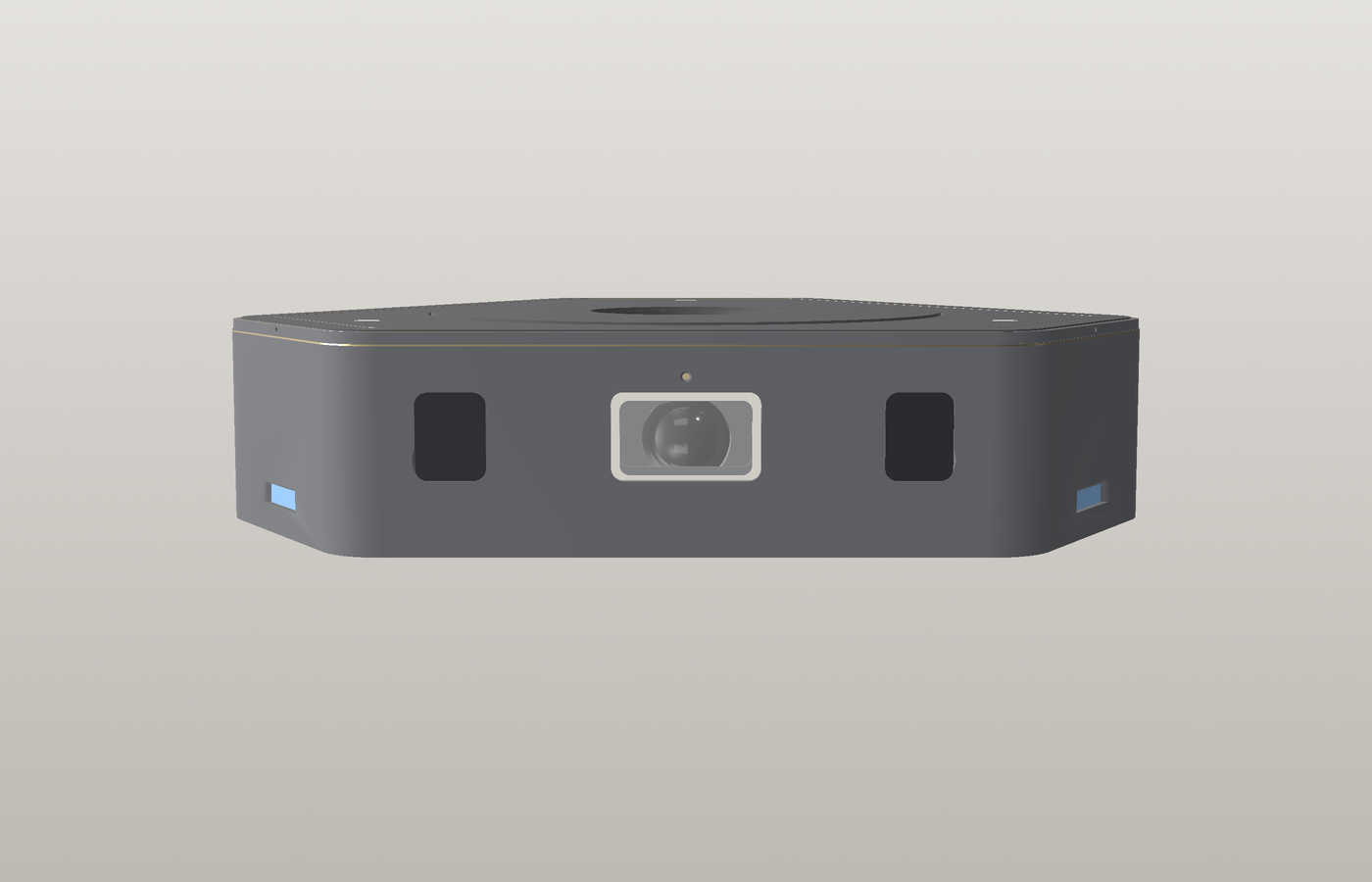
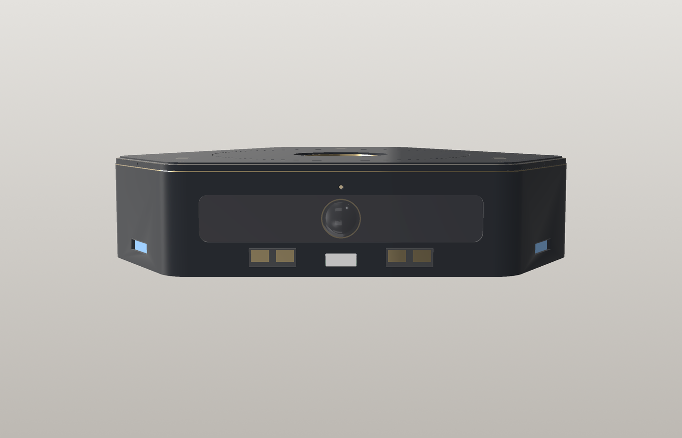
S1 / W3 + K1 rev2 · Sept 24–26, 2026 · rendered from CAD, not a photograph
The current revision
A cleaner exterior. A harder integration problem.
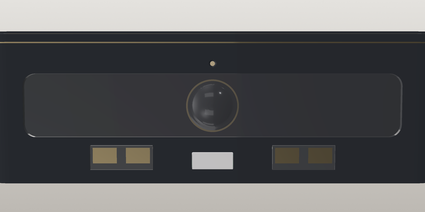
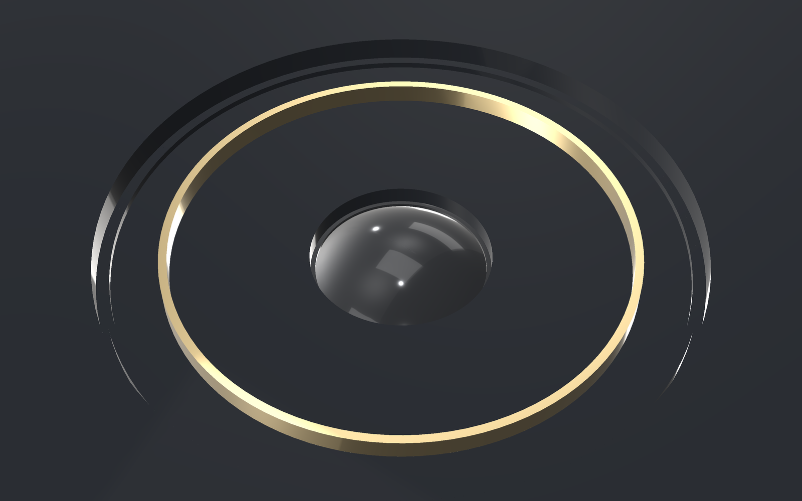
Three separate windows on each camera face became one flush black visor. The top became a smooth floating cup deck with a fixed gold camera ring. Under that surface, the work is about optical clearance, load paths, power protection and making the wiring serviceable.
The renders show the latest S1 exterior, not every subsequent internal board or harness revision. Current electrical and integration status is broken out below.
Packaging target39 mm height · three-omniwheel holonomic drive
Current limitHarness integration, supplier interfaces and first-article tests remain open
W3: one flush visor per camera faceK1 rev2: no exposed silicone; hard labyrinth light sealCH1 rev1: dock contacts + USB-C board, internal CAD
Mechanical + optical integration
Visor and floating deck
The visor hides the edge-sensor windows behind IR-transmitting black print while leaving the camera aperture clear. K1 rev2 replaces the silicone top with a gloss deck, fixed lens bezel and a labyrinth seal that allows the deck to move.
Recorded CAD checks: 436 visor/pan neighbour pairs with no intersections; 72 ToF probe cones unobstructed. Deck travel was checked at ±0.30 mm vertically and ±0.35 mm laterally.
These are scoped geometry checks, not optical, grip, spill or durability tests on hardware.
Electrical integration · Sept 26
Mainboard and charging
E12 rev5 integrates Hall-sensor interfaces, motor power/braking circuitry and the CH1 charging connections. CH1 rev1 adds four flush dock-contact pads and USB-C charging/data, with reverse-blocking protection and dock-priority circuitry.
Recorded E12 checks: 0 ERC violations; 0 DRC violations, unconnected items or schematic-parity issues under the configured rules. Eight-layer fabrication outputs were generated.
Not fabrication approval. Some rule categories are ignored; thermal behaviour, USB signal quality and complete-system integration still need review and measurement.
Interfaces + sourcing
Designing beyond the shell
The Spire S12 dock study aligns its charging contacts and transfer geometry to the coaster. The Atlas interface defines V-slot capture and a proposed camera-guided alignment handshake. Neither docking nor aircraft pickup has been demonstrated.
BOM snapshot: B1 rev2 tracks 110 lines: 63 marked orderable, 8 awaiting suppliers and 39 design-open as of September 26.
The BOM snapshot predates the final E12 rev5 changes and needs reconciliation. Compute, camera and battery supplier details remain unresolved; no orders are being placed.
A finding that changed the design
The “window edge” was actually a hole.
A dark crescent next to a ToF window looked like a styling problem. Sectioning the CAD showed that an angled sensor tunnel broke through the shell up to 0.43 mm beyond the window pocket. The old flushness check had checked for protrusions, not missing wall material.
W3 extends the visor pocket over the breakout and adds face-plane and perimeter checks. That fixed the modeled opening—but the thinner visor also increased the modeled sensitivity to smudges. Moving the ToF sensors farther forward remains a proposed follow-up, not a completed fix.
Before · W2 separate windowsAfter · W3 continuous visor
Latest development timeline Sept 22–27, 2026
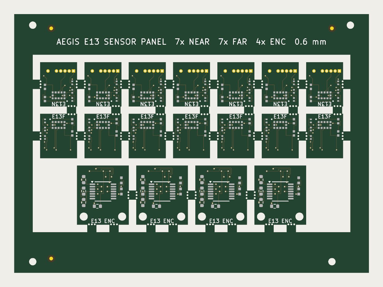
Board, vision and interface work. E12 mainboard revisions, routed A4 microphone-capture and E13 sensor boards, four-camera coverage studies and the Atlas capture interface. These are design packages, not working V2 electronics.
S1 / W3 and K1 rev2. Continuous black visors, concentric camera apertures, gold accents and a silicone-free floating deck. Optical and mechanical checks documented alongside their limitations.
E12 rev5, CH1 rev1 and Spire S12. Charging and connector revisions, regenerated PCB outputs and dock-interface geometry work. The 110-line BOM records sourcing and remaining design gaps.
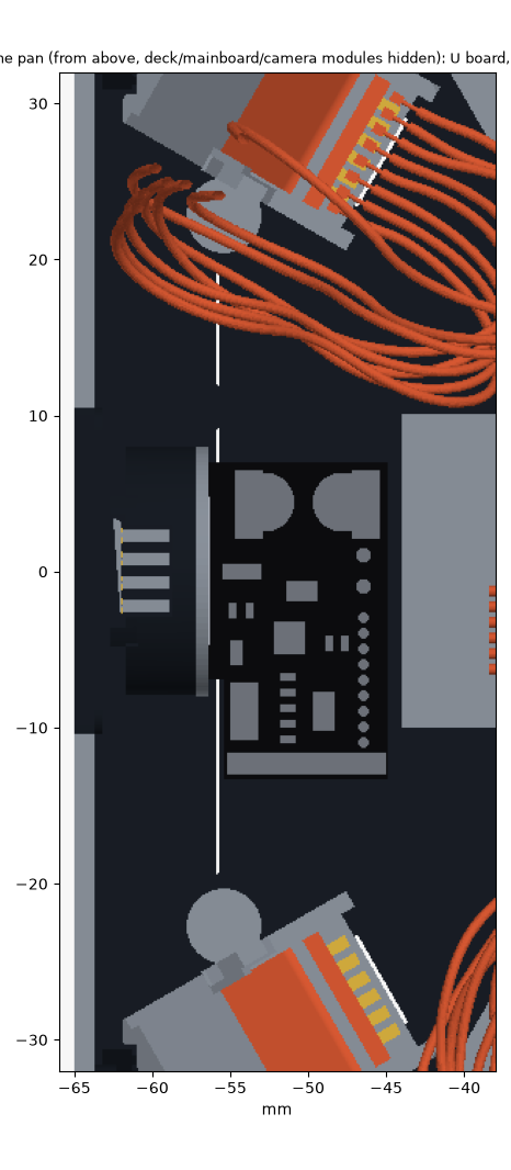
Harness and force-board integration paused mid-revision. H6 still has conflicting or unrouted branches, including the IMU/encoder route and microphone exits. K2 rev2 board routing was checked, but its mechanical placement, harness and fabrication outputs were not completed.
V1 manual-drive debugging. Encoder-feedback driving resumed; a low-power watchdog defect was reproduced and patched with regression tests. Details are in the V1 update below.
Earlier CAD, physical form study and concept film
These show earlier stages of the project, not the current W3 exterior or E12 rev5 internals. The full-size exterior print is a form study, not a functional V2 assembly.
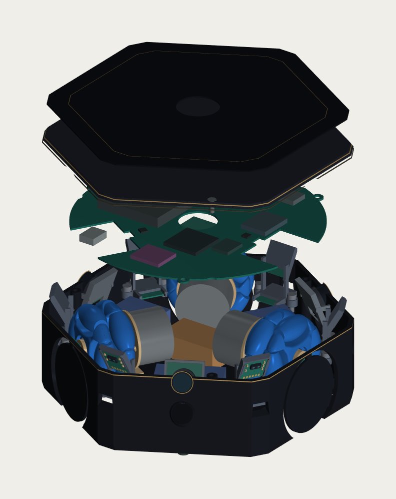
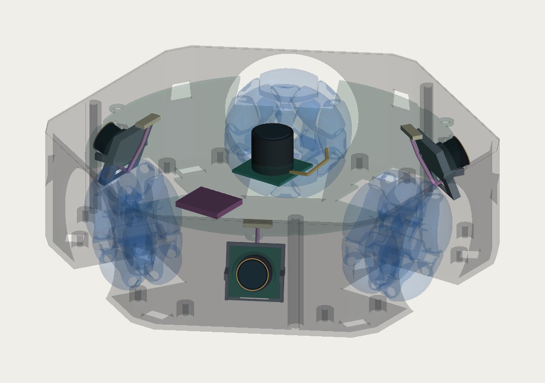
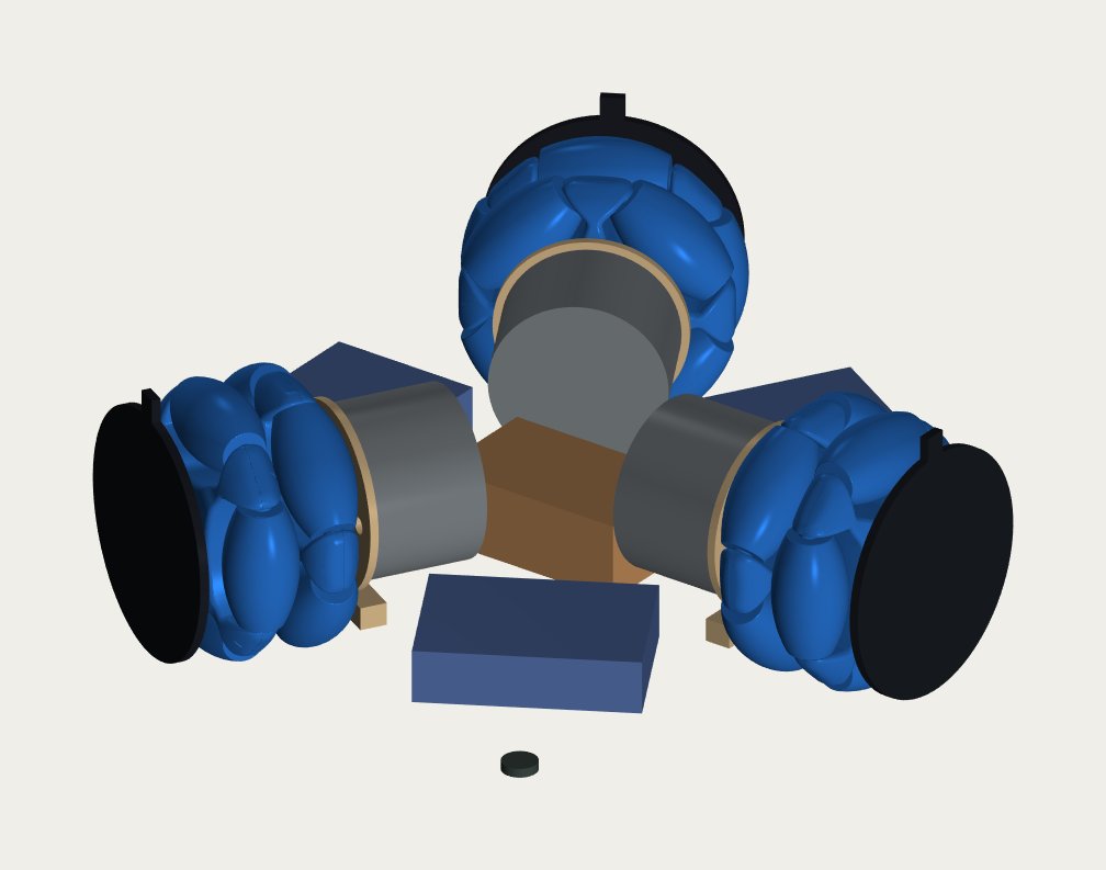
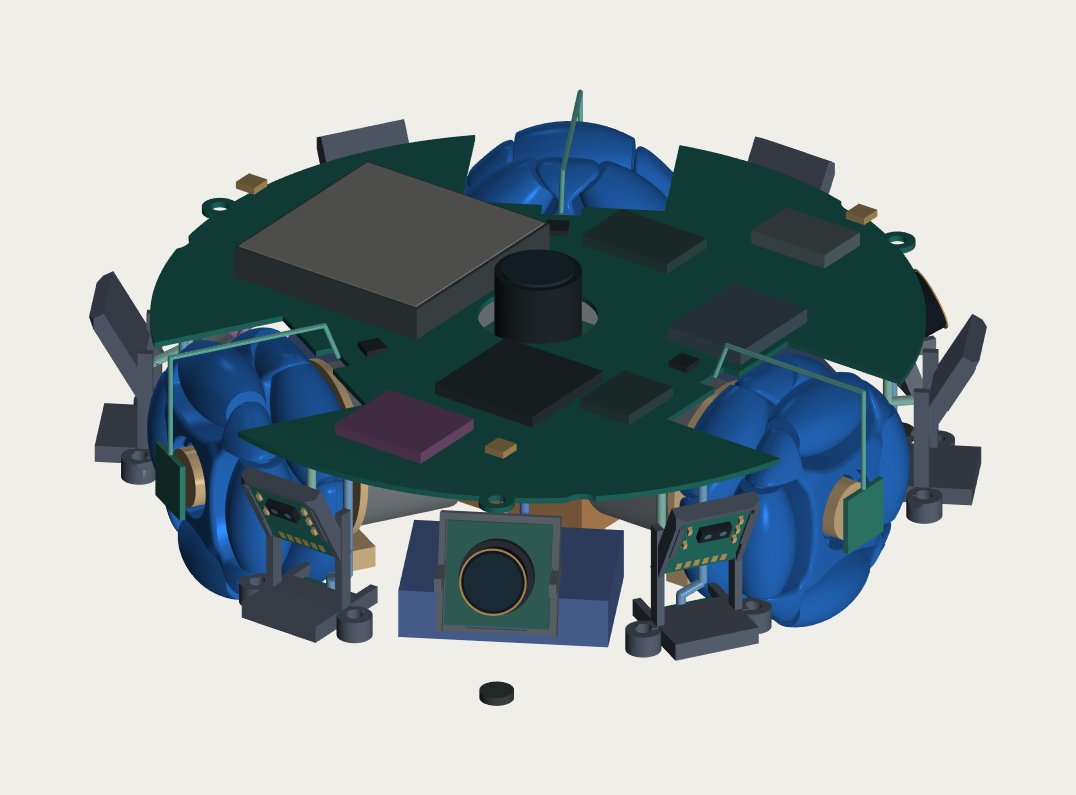
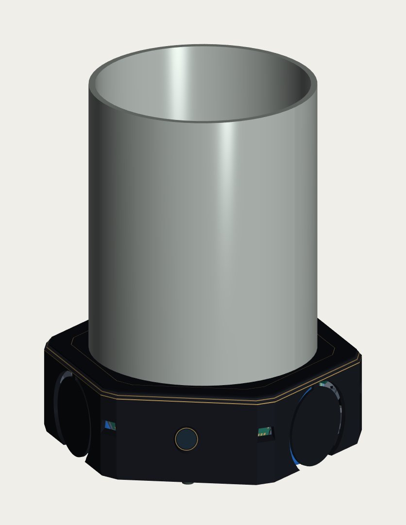
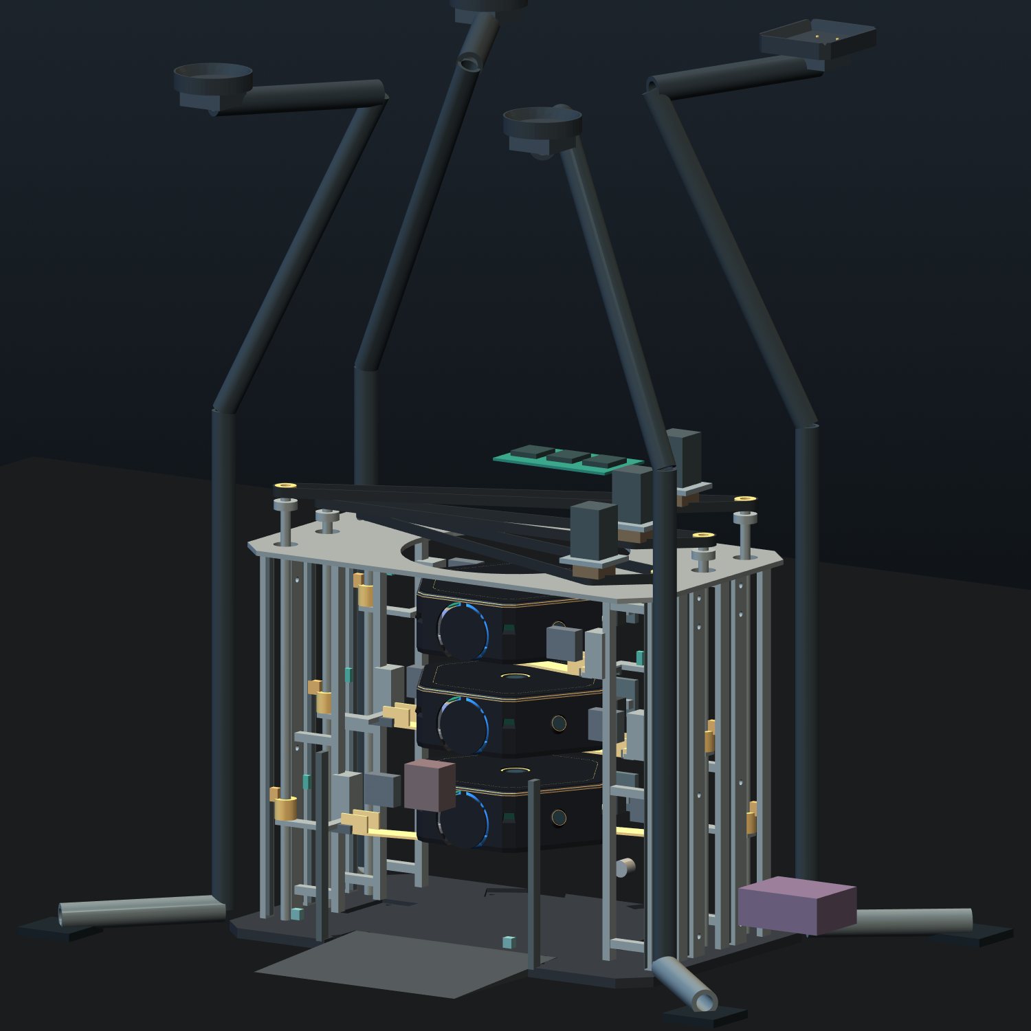
Earlier assembly · exploded CADE13 panel · PCB render, not fabricatedEarlier camera-layout studyDrive-cartridge design studyEarlier packaging studyCup-on-deck concept renderPhysical exterior form study · nonfunctionalD4 dock concept · superseded by Spire workEarlier D4 cutaway
The 74-second film illustrates the intended experience. It is AI-assisted concept imagery, not filmed robot performance and not a record of the latest CAD revision.
Portfolio updated September 29, 2026 · based on engineering records through September 27.
02 — Aegis V1 · 2025 → 2026 · built & running
Build log
V2 exists because V1 got built. From the first 2025 test rigs to the R12-C1 prototype in 2026: physical assembly, encoder feedback and the problems I had to solve to make it move.
Latest hardware update · September 27, 2026
R12-C1: encoder-feedback manual driving
The printed chassis has three motors and encoders connected to a Raspberry Pi / Motoron drive system, with a Seeed XIAO ESP32-S3 handling encoder feedback. Manual driving uses a DualSense controller and conventional wheel-speed feedback.
A no-progress watchdog was counting low-power time toward its stall timeout, which could stop a wheel immediately when the command crossed the threshold. With AI-assisted debugging, the timer logic was corrected; two regression cases reproduced the defect before the fix and 80 relevant tests passed afterward, including the blocked-wheel case. I subsequently confirmed manual driving after recovering a separate motor-supply interruption.
This establishes working manual control, not autonomous cup placement or validated spill-free motion. The vision/metric-pursuit software and real contact sensing are not yet integrated into the deployed controller. The videos below are the earlier 2025 builds, not footage of this R12-C1 revision.
Aug 2025 · Iteration 1
Extrusion-frame test rig
80/20 aluminum frame, three omniwheels, a breadboard and a rat's nest of jumpers. Driven from a keyboard to prove out the holonomic wheel mixing before any electronics got finalized.
Aug 2025
First controlled motion
Translation and rotation on the floor, tethered to a bench supply. Tuning the wheel angles (90° / 210° / 330°) until "forward" actually meant forward.
Sep 2025 · Iteration 2
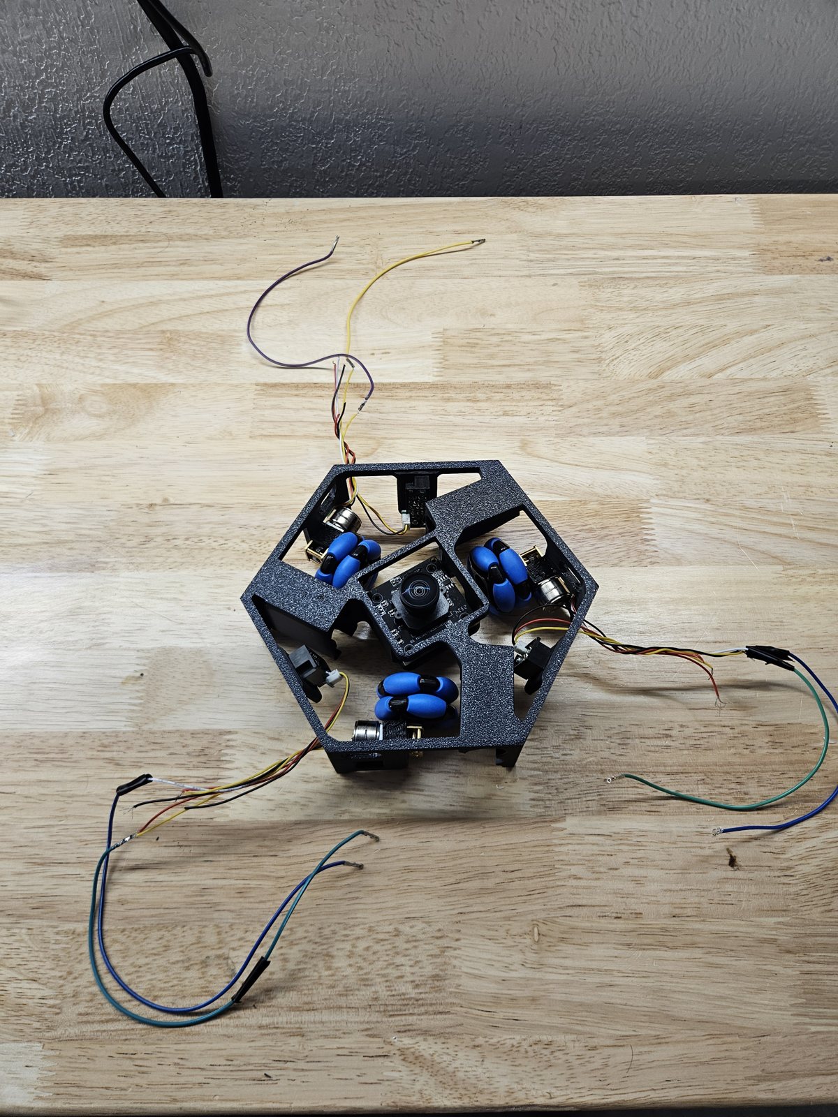
Compact printed chassis
Designed in SolidWorks and 3D printed. Three N20 gearmotors in a hex frame, sized to sit under a cup. Wiring, connectors and power distribution done by hand.
Sep 2025
Gesture response
Raspberry Pi 5, Pololu Motoron driver and an upward camera. The robot follows a hand moving above it, with Python control running on the Pi.
Problems I diagnosed
Symptom
One wheel went dead mid-testing.
Root cause
Over-voltage. A 7.4 V pack was driving 6 V-rated N20 motors, and full-power stall tests finished one off.
Change
Initially added a software duty cap, then selected matched 12 V encoder motors. A duty cap does not limit stall current or replace correctly rated power hardware.
Symptom
After swapping in a replacement motor, the robot spun instead of translating.
Root cause
The replacement was 30 RPM against 220 RPM on the others. A holonomic base needs matched wheels, and you can't out-gain a top-speed mismatch in software.
Change
Replaced all three with matched encoder motors. The current R12-C1 manual-drive system uses encoder-feedback wheel-speed control.
Symptom
Cup tracking kept locking onto arms, paintings and people.
Root cause
An upward camera only sees the cup as a shadow against the ceiling. That signal can't reliably tell a cup from anything else overhead.
Fix
Re-architected perception around a retroreflective IR marker: a NoIR camera, an 850 nm LED ring and an IR-pass filter, so the marker glows and everything else goes dark. The detector and its tests are written, and hardware bring-up is in progress.
Symptom
Motion was jerky enough to slosh a drink.
Root cause
Raw PD output was sent straight to the wheels, with no limits on acceleration or jerk.
Change
Developed AI-assisted motion-planning software with a jerk-limited profiler, an α-β target predictor and a curvature speed limiter. Software tests are separate from the deployed manual controller; this is not a demonstrated spill-free autonomous run.
03 — Helios smart mirror · 2025 → 2026
Helios
A mirror that turns to keep your face centered as you move around the room. Version 1 is built and tracking. Version 3 is redesigned so it can move faster than your eye.
Helios V3 · the real CAD · in designpan 0° · tilt 0°
Move your cursor over it and it tracks you
3D view unavailable in this browser
130 msplanned 60° tilt move. A human eye takes about 153 ms.
0.03 mmcentre of mass from the tilt axis, so the servo doesn't fight gravity.
6.13 kgtotal, including 3.2 kg of steel-shot ballast so the pan snap can't slide it.
100 % printedon a Bambu A1, held together with stock M2/M3 hardware only.
Helios V1 tracking, with the live detection feed on screen
V1 → V3
V1 (built): pan/tilt servo head designed in SolidWorks and 3D printed, dual side-mounted cameras, Python/OpenCV face detection and velocity-limited servo tracking.
V2 (built): scaled up to a 9 × 9 in two-way glass pane with the camera behind it. It worked, but the 1.07 kg of glass hung about 200 mm in front of the tilt servo, so it had to be tuned slow to stop it oscillating.
V3 (in CAD): keeps the same glass and carries it on trunnions through its centre of mass. The tilt servo drives it directly, the pan runs on two bearings in a ballasted base, and servo power moves to a dedicated 8 V supply. Every part is checked for interference, balance, tipping and printability before anything is printed.
04 — Hestia heater orb · 2026 · design study
Hestia
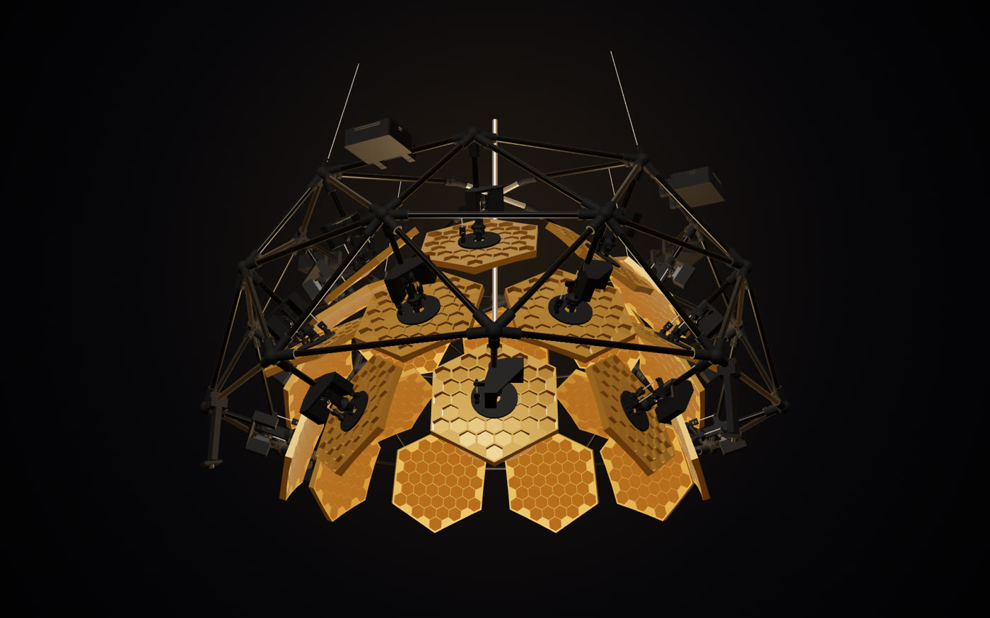
An outdoor heater that gives every guest their own sun. One halogen star hangs in a gold chalice inside a crown of twenty-six concave gold mirrors, each on its own tip-tilt joint. Thermal cameras find the people at the table, and the mirrors aim the star's infrared at them instead of heating the air.
Hestia A2 · the real CAD · running its own controller26 mirrors
3D view unavailable in this browser
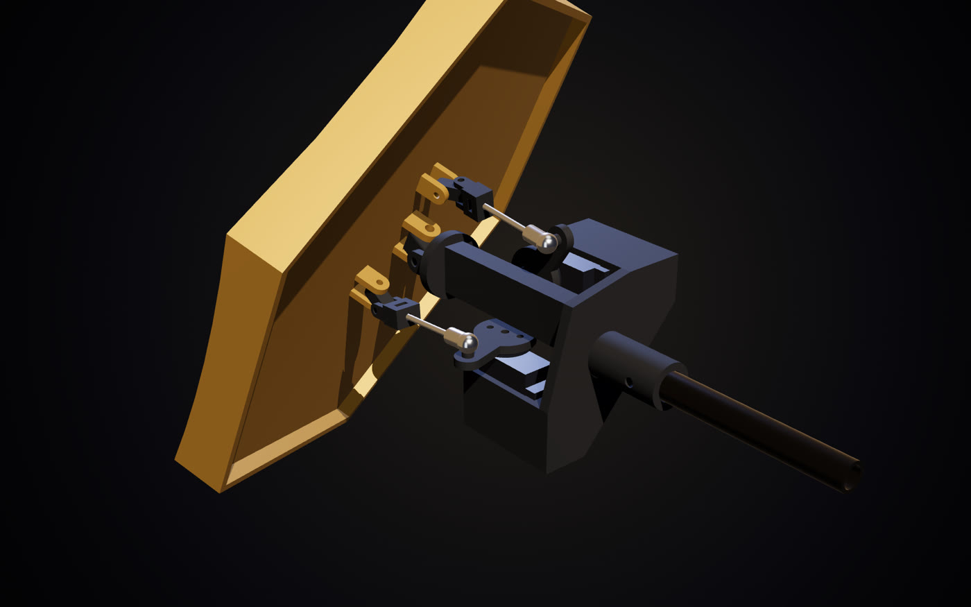
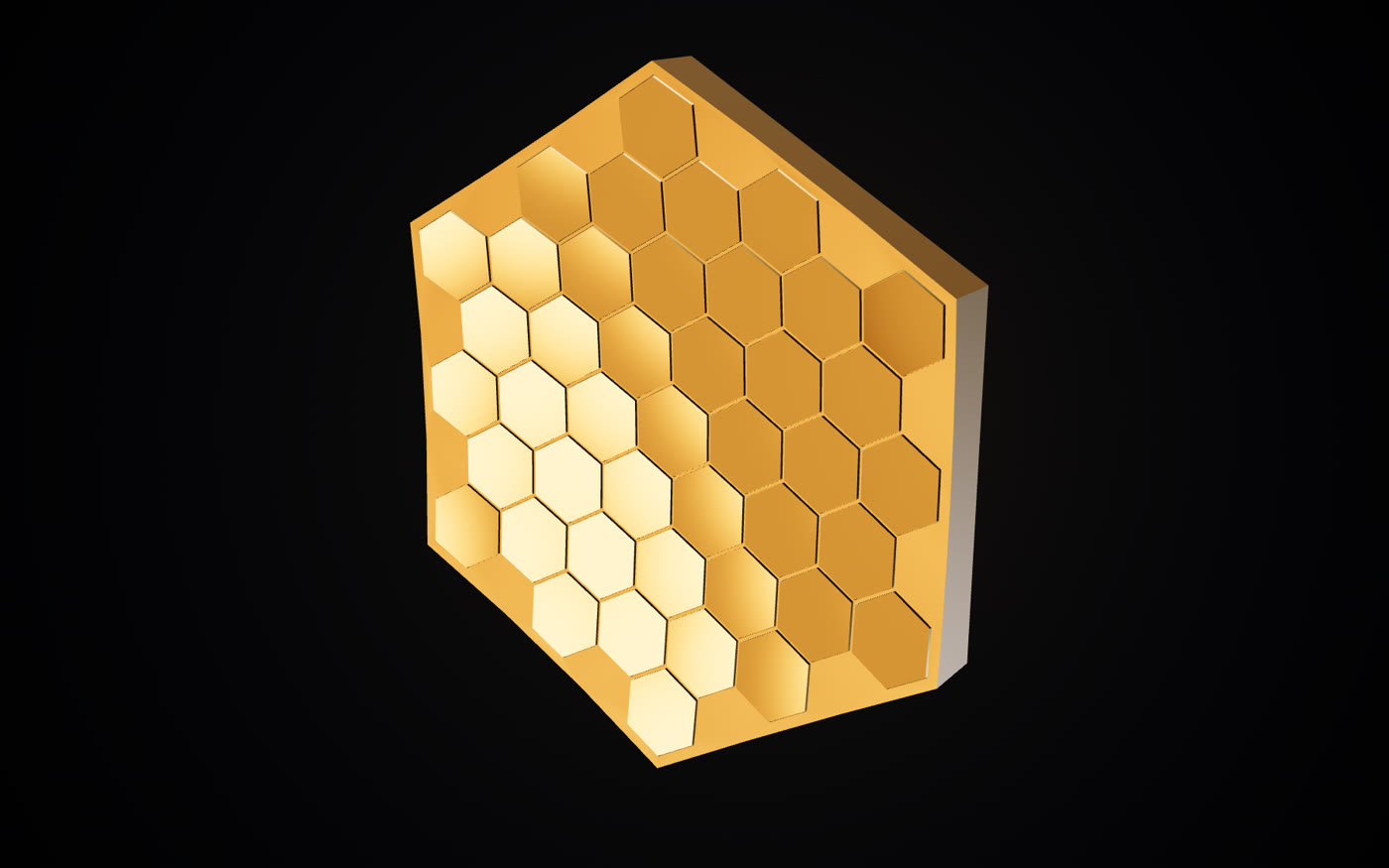
26 mirrorseach 43 one-inch gold tiles in a printed concave dish, tipped and tilted by two servos through pushrods.
2.1×the warmth of a pendant heater on the same plug for the coldest guest at a four-top: +5.8 °C felt, ray-traced.
≤ 58 W/m²of IR on any face under the controller's own plans, against a safety limit of 100. A pendant heater puts 150–160 there.
13 / 13design checks pass, from mirror collisions and servo load to heat, hanging load and camera coverage.
The crown: 26 modules on a carbon frameTip-tilt module: offset U-joint, two servos, pushrods43 gold tiles on a concave dish
A guest walks around the table, and the mirrors follow
How it works
The star: two 750 W halogen capsules run at about 1311 W. A mirror can only aim light from a small, bright source into a tight spot, so the source has to be compact.
Chalice and dome: spun, gold-plated caps that send stray light back through the star to the mirrors, and hide the star itself from every seated guest.
The modules: each dish rides an offset universal joint just behind its tiles, driven by two servos through M2 pushrods, anywhere in a ±40° cone. Holding a dish against gravity takes under 10 % of a servo's stall torque.
The brain: an ESP32-S3 and three thermal cameras that find warm bodies without imaging faces. It plans which mirror serves whom, keeps neighbouring mirrors apart, lets each spot "breathe" over the torso, and dims the star to a skin limit. The model above runs that same controller, ported line for line from the firmware.
How it's built: every number here comes from scripts in the design repo: a Monte Carlo ray tracer, thermal models, CadQuery parts and thirteen pass/fail checks. 40 print files (6.6 kg of PLA) and stock M2/M3 hardware. It's a design study: nothing is built or ordered yet.
05 — More
Also built
2024 · Founder & technical lead
Drive Systems Technologies
I led a three-person team on a pressure-fed ethanol/nitrous rocket engine with nitrogen pressurization, covering plumbing design, control software and early fabrication.
I also set up the shop from scratch. I bought and moved a Bridgeport mill and two lathes, got three-phase power running, and ran the forklift.
2026 · Software product
Array Operator
A solar-operations platform I built and deployed. It pulls inverter and utility-bill data, tracks long-term performance, has an AI agent that answers operational questions, and automates reporting and maintenance email.
Mechanical engineering coursework to junior standing (2022–2024): statics, dynamics, materials, thermodynamics, circuits, manufacturing, CAD and programming.
Forklift certified.
06 — Off the clock
MindSpace
A seven-minute generative film, cut to music. A swarm of glowing "minds" blooms out of a star, rings it in cards, and grows a web of light, every move landing on the beat.
the swarm unfolds on the drop · sound off
How it was made: I set the vision and directed every cut. AI coding agents wrote the code in real-time 3D, each one owning its own "mind", working against a shared song clock and an architecture doc I kept up to date.
Scale: about 100 commits in a week, re-rendered and re-cut from my notes on each version.